- 您现在的位置:买卖IC网 > Sheet目录226 > GB15JVC (NKK Switches)SWITCH PUSH SPDT 0.4VA 28V
Series GB
Ultra-Miniature Fully Illuminated Plungers
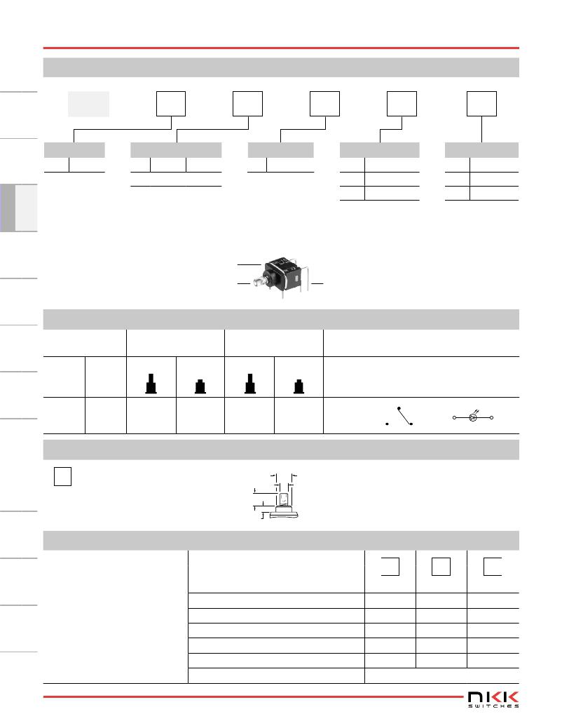
TYPICAL SWITCH ORDERING EXAMPLE
GB
Pole
1
Circuit
5
Actuator
J
H
PC Terminals
F
LEDs
1
SPDT
5
ON
(ON)
J
Clear
P
Straight
C
Red
( ) = Momentary
H
V
Right Angle
Vertical
D
F
Amber
Green
D
DESCRIPTION FOR TYPICAL ORDERING EXAMPLE
GB15JHF
SPDT
ON-(ON) Circuit
Clear Plunger, Green LED
POLE & CIRCUIT
Right Angle PC Terminals
Plunger Position
( ) = Momentary
Connected Terminals
Throw & Switch/Lamp Schematics
Pole
Model
Normal
Down
Normal
Down
Note: Terminal numbers are not actually on
the switch. LED circuit is isolated and
requires an external power source.
SP
GB15
ON
(ON)
5-6
5-4
SPDT
4
5 (COM)
6
(1)
(3)
ACTUATOR
J
Clear Plunger
(4.0) Dia
.157
(2.0) Dia
.079
(3.3)
.130
(1.6)
.063
LED COLORS & SPECIFICATIONS
LEDs are an integral part of the
switch and not available separately.
The electrical specifications shown
are determined at a basic tempera-
ture of 25°C.
If the source voltage exceeds the
rated voltage, a ballast resistor is
required.
The resistor value can be calculated
by using the formula in the Supple-
ment section.
Forward Peak Current
Typical Forward Current
Forward Voltage
Reverse Peak Voltage
Current Reduction Rate Above 25°C
Ambient Temperature Range
Colors
I FM
I F
V F
V RM
?I F
C
Red
30mA
20mA
1.9V
5V
0.43mA/°C
D
Amber
30mA
20mA
1.9V
5V
0.43mA/°C
–25° ~ +55°C
F
Green
25mA
20mA
2.1V
5V
0.36mA/°C
D10
www.nkk.com
发布紧急采购,3分钟左右您将得到回复。
相关PDF资料
GCC50DCSN-S527
CONN EDGECARD 100POS .100 EXTEND
GDE25-1
TRANSF .350 OHM SINGL GATE DRIVE
GDE25-2
TRANSF .650 OHM DUAL GATE DRIVE
GDE25-3
TRANSF .350 OHM SINGL GATE DRIVE
GDE25-4
TRANSF .650 OHM DUAL GATE DRIVE
GDE25-5
TRANSF .875 OHM SINGL GATE DRIVE
GDE25-6
TRANSF 1.75 OHM DUAL GATE DRIVE
GECA20-24G
PWR SUP 24V 0.84A 3.5X2X0.85
相关代理商/技术参数
GB15JVC-RO
功能描述:按钮开关 SPDT ON-(ON) 0.4VA
RoHS:否 制造商:C&K Components 触点形式:2 NC - 2 NO 开关功能:ON ? OFF 电流额定值:4 A 电压额定值 AC:12 V to 250 V 电压额定值 DC:12 V to 50 V 功率额定值: 安装风格:Through Hole 照明:Illuminated 照明颜色:None IP 等级:IP 40 端接类型:Solder 触点电镀:Silver 执行器:Square 盖颜色: 封装: 可燃性等级:UL 94 V-0
GB15JVD
制造商:NKK Switches 功能描述:ULTRA MINIATURE PUSHBUTTON/ILLUM 制造商:NKK Switches 功能描述:ULTRA MINIATURE PUSHBUTTON/ILLUMINATED/PC
GB15JVD-RO
功能描述:按钮开关 SPDT ON-(ON) 0.4VA
RoHS:否 制造商:C&K Components 触点形式:2 NC - 2 NO 开关功能:ON ? OFF 电流额定值:4 A 电压额定值 AC:12 V to 250 V 电压额定值 DC:12 V to 50 V 功率额定值: 安装风格:Through Hole 照明:Illuminated 照明颜色:None IP 等级:IP 40 端接类型:Solder 触点电镀:Silver 执行器:Square 盖颜色: 封装: 可燃性等级:UL 94 V-0
GB15JVF
功能描述:按钮开关 SPDT ON-(ON) 0.4VA GRN VERTICAL PC
RoHS:否 制造商:C&K Components 触点形式:2 NC - 2 NO 开关功能:ON ? OFF 电流额定值:4 A 电压额定值 AC:12 V to 250 V 电压额定值 DC:12 V to 50 V 功率额定值: 安装风格:Through Hole 照明:Illuminated 照明颜色:None IP 等级:IP 40 端接类型:Solder 触点电镀:Silver 执行器:Square 盖颜色: 封装: 可燃性等级:UL 94 V-0
GB15JVF-RO
功能描述:按钮开关 SPDT ON-(ON) 0.4VA
RoHS:否 制造商:C&K Components 触点形式:2 NC - 2 NO 开关功能:ON ? OFF 电流额定值:4 A 电压额定值 AC:12 V to 250 V 电压额定值 DC:12 V to 50 V 功率额定值: 安装风格:Through Hole 照明:Illuminated 照明颜色:None IP 等级:IP 40 端接类型:Solder 触点电镀:Silver 执行器:Square 盖颜色: 封装: 可燃性等级:UL 94 V-0
GB15RF120K
功能描述:IGBT 模块 25 Amp 1200 Volt Non-Punch Through RoHS:否 制造商:Infineon Technologies 产品:IGBT Silicon Modules 配置:Dual 集电极—发射极最大电压 VCEO:600 V 集电极—射极饱和电压:1.95 V 在25 C的连续集电极电流:230 A 栅极—射极漏泄电流:400 nA 功率耗散:445 W 最大工作温度:+ 125 C 封装 / 箱体:34MM 封装:
GB15RF60K
功能描述:IGBT 模块 25 Amp 600 Volt Non-Punch Through RoHS:否 制造商:Infineon Technologies 产品:IGBT Silicon Modules 配置:Dual 集电极—发射极最大电压 VCEO:600 V 集电极—射极饱和电压:1.95 V 在25 C的连续集电极电流:230 A 栅极—射极漏泄电流:400 nA 功率耗散:445 W 最大工作温度:+ 125 C 封装 / 箱体:34MM 封装:
GB15XF120K
功能描述:IGBT 模块 25 Amp 1200 Volt Non-Punch Through RoHS:否 制造商:Infineon Technologies 产品:IGBT Silicon Modules 配置:Dual 集电极—发射极最大电压 VCEO:600 V 集电极—射极饱和电压:1.95 V 在25 C的连续集电极电流:230 A 栅极—射极漏泄电流:400 nA 功率耗散:445 W 最大工作温度:+ 125 C 封装 / 箱体:34MM 封装:
